Fork Fixture
The next step in building my new bike is making a fork. To make a fork I needed a fork fixture. I built this one using 80/20 extrusion and a few simple machined pieces.
The design was influenced by two sources. Mike Flannigan (ANT Bike) posted this photo of a 80/20 fork fixture on his flickr a few years ago:
Jeff Lyon told me last year that he felt like fork jigs should hold the fork blades curving into the backbone of the jig, rather than away from it. That makes the dummy axle support a little more reasonably sized when building high offset forks.
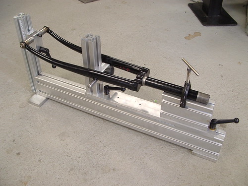
This is what I’ve built:
You’ll notice that is is pretty similar to Mike Flannigan’s fixture. I consider it a workable prototype. There are a few tweaks that I’d make on the next one, but this is working well for me.
There are two major sub-assemblies here that connect to a piece of 1020 which acts as a backbone. On the left you can see the vertical dummy axle riser and dummy axle mounted to it. The dummy axle can be moved up or down to hit a target amount of offset. A scale should be added to indicate the amount of offset.
On the right there is a sliding assembly which holds the steerer tube and the fork blades just below the crown. This can be moved on the backbone as a single unit to build forks of different heights. It is locked in place using two bolts. That sliding assembly in turn contains a vertical support for the blade support and a steerer clamp. This photo shows the sliding assembly from a different angle:

The steerer clamp is made from 1030 extrusion (that is 1″ wide, 3″ tall). I machined off the top of the extrusion, making a V that can hold the steerer. There are bolts that run down through the extrusion to the T-nuts that lock it into the piece below it. The toggle clamp is attached using a small section of aluminum angle stock and a 1/2″ thick block which acts as a spacer.


The dummy axle is compatible with Anvil ones (so a nicer Anvil dummy axle could replace it in the future). It has a 2.5″ wide 1/2″ diameter center section. I made the dummy axle holder using a 1/2″ ball end mill to cut the grooves. It secures to a piece of 1″ wide 80/20 extrusion using a double T-nut. All of those parts are in the top of the next photo. It is important that the back of the dummy axle holder has grooves which can slide accurately in the 80/20 to keep everything square. They also must be centered to hold the dummy axle in the centerline of the extrusion.
The lower part makes up the fork blade support. This is some 5/8″ round extrusion which I milled slots that can ride in 1″ wide 80/20 stock. This is held in place with a single T-nut.

This photo shows how the dummy axle support fits together:

I have two vertical pieces of 80/20 on the jig and tried two different methods of attaching them. The one for the dummy axle has plates which clamp from the side. These are easy to work with and keep the vertical portion square to the horizontal portion:

80/20 also makes special fasteners which fit into a hole milled into the end of the horizontal piece. They are lower profile, but I found it more difficult to keep everything square when tightening them:

I’ll finish this up with a parts list. The parts list has a few corrections that I’d make to this fixture (like using plates in the photo above instead of the special 80/20 fastener).
All extrusion lengths are rough, being too long doesn’t really hurt anything. There is a drawing at the bottom which I think has the “ideal” lengths. My prototype jig was built using what I had on hand. The easiest source for 80/20 parts is the “80/20 Garage Sale” on eBay.They sell most of the stuff in the catalog and have very reasonable shipping (ignore the shipping quoted for parts, just put together a large order and they’ll email you a quote).
-
24″ long piece 1020 for the backbone.
-
2 pieces of 8″ of 1010 for the dummy axle and fork blade holder risers.
-
1 piece of 10″ long1010 for the sliding assembly.
-
1 piece of 4″ long 1030 extrusion for the steerer holder.
-
Economy T-Nuts with 1/4-20 threading (style 3382):
-
2 for holding the sliding assembly to the backbone
-
1 for the fork blade holder
-
2 for the holding the angle stock which supports the toggle clamp to the steerer holder
-
Double economy T-nuts with 1/4-20 threading (style 3280):
-
12for the side plates to hold the vertical supports
-
1 for the dummy axle holder
-
Economy T-Nuts with #10-32 threading (style 3276):
-
2 for holding the steerer V-block to the sliding assembly. I recut the threads to M5×0.8mm pitch because I have many more M5 bolts than #10 bolts.
-
2 of the4166 joining plates for holding the dummy axle riser to the backbone. These plates have 6 holes and are rectangular. I think they’d work better than the triangular plates that I used (but I already had those on hand).
-
2 of the 3321 joining plates for holding the fork blade support riser to the sliding assembly. These plates are L-shaped with 5 holes. I think one hole could be cut off and they’d still be plenty secure.
-
Roughly 1 foot of 6702 double keyed UHME sliding material. I cut this into 3 4″ sections. One goes between the steerer support and the sliding assembly. The other two pads go between the sliding assembly and backbone. This material is useful because it slides nicely and keys the sections together, keeping them in tight alignment.
Material needed for other bits:
-
The bottom of the dummy axle support is 2.5″ wide by 2″ tall by 1/2″ thick aluminum.
-
The top is 1″ wide by 2″ tall by 1/2″ thick aluminum.
-
The angle stock for the toggle clamp is just 1.5″ x 1.5″ aluminum angle that is about 3/16″ to 1/4″ thick.
-
The toggle clamp spacer is any stock that is at least 1/2″ thick and 1″ tall.
-
The dummy axle is 5/8″ diameter 303 stainless steel.
-
The fork blade support is 6″ long of the same 5/8″ diameter 303.
Here is my original drawing for this fixture (click for huge):

Building this does require a milling machine for making the dummy axle holder, fork blade holder, and for modifying the 1030 extrusion. I’d guess that this is about 2 hours of milling time for a moderately experiencedoperator. A lathe is necessary to make the dummy axle, but you could buy a very nice Anvil dummy axle instead of using a lathe.


