Archive for the ‘Framebuilding’ Category.

Lots of projects brewing

Here is a single photo with 3 of the 4 that I’m writing about today:

First up is what I’m calling the Ivy-T. It is the replacement for my RB-T that I’ve been using as my commuter and road bike for the last few years. The new bike is sort of a joint project between Brandon Ives (IvyCycles) and I. He built the frame, I’m going to be doing the final bits on it (bridges, brazeons, brake bosses) and making the fork and rack. The geometry is basically a 56cm 1994 Bridgestone RB-T with the seat tube extended to 59cm, the top tube extended a bit, and a slightly sloping top tube. The lugs are Prugnat-style fromLong Shen. The tubing is Kaisei 019 (0.8mm/0.5mm/0.8mm butting, standard diameter) and the dropouts are Paragon verticals. It is a pretty light frame right now at around 3lbs, 12oz. I expect it’ll be more like 4 pounds once I’m done with it. Brandon’s work look very good and I look forward to finishing this one up.

Click the headtube for more photos:

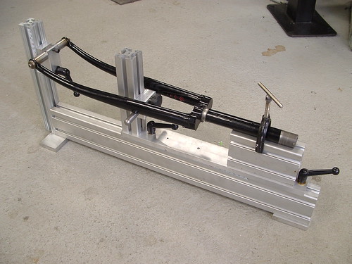
Next up is a rack for Christine’s new bike.I’ve made about 80% of the deck, I still need to put in 3 more rays for the sunburst. We ordered a custom bag for her bike from Swift Industries. I’m going a little outside my normal with the rack and making the rack a little more pretty than what I would normally do. The pattern on the deck is influenced by anAhearne rackfrom the 2007 NAHBS.

John Speare gave Rory his beloved (or behated) Fuji Turd. Rory is turning it into a cycle truck, which I guess will probably become called the Turd Hauler (John calls the first cycle truck that we built the Stuff Hauler). Rory came over this morning and we mitered the cargo tube and top tube. When I built the first cycle truck a few years ago that process took me at least a full day. This time we did it in about 2 1/2 hours, including at least 30 minutes of searching for my 1 3/4″ tube clamp. Experience and a good milling machine do speed things up. Click the image for some iPhone quality images that Rory took of the process this morning.

Finally, I’ve been meaning to write about my new CNC mill for at least a month,but haven’t gotten around to it yet.

I bought this two months ago from Craigslist as a birthday present to myself. It is a Taig (made in the US) benchtop 3-axis CNC mill. What does that mean? The mill can move an object in two axis (X and Y),and then lower a tool (like a drillbit) from above in the third Z axis. CNC means that acomputer does the tedious work of moving the work around and cutting metal. Since computers don’t get bored it is happy tolots of timecutting out pretty intricate stuff. My first project with it was programming in all of the parts for the fork jig and making another fork jig for a fellow framebuilder. Once I have some feedback on it I plan on making some more. I’ve also used the CNC mill to make some simple fork dropouts (for yet another project) and lots of little fixtures.

In this photo it is making some brackets for the fork jig:

Here is what the computer shows while doing the heavy work:

The final result only requires a tiny bit of hand cleanup:

Fork fixture V2, almost all of the parts were made on the CNC mill.On the lower right corner you can see one of the brackets that the mill was cutting out above.

I plan in following up with more CNC stuff in a future posting, including some videos of it in action. For now I’m still mostly in the learning stage.

Gifford

The TODO list is getting short, and got short enough for me to build it up for some shakedown rides. Remaining on the list:

  • Wire guides for the headlight
  • Racks (this one is borrowed from my RB-T)
  • Paint

A couple of small details. This is how I routed the cables to the Rohloff (always a little tricky):

The wire guides are cut up and bent pieces of a spoke. I liked them better than the commercial guides that I could find. Running the cables over the bottom bracket and then around the inside of the chainstay gave me a much nicer cable run than under the bottom bracket (which is very large on this bike).

Tire and crank clearance came out just about perfectly. A 2″ or 52mm knobby fits and so do my lowish Q-Factor Ritchey cranks.

I removed the big ugly Rohloff sticker from the hub (now that my warranty is expired):

It weighs 30# as shown. A little chunky, but not too bad fora Rohloff’d bike with fenders, racks, pump, water bottle cages, etc.

I’ve named it Gifford in honor of Gifford Pinchot, since I expect that this bike will spend a good amount of time (and the most enjoyable time) in National Forest lands.

Brief set of geometry specs:

  • 55cm seat tube (actual), 58.5cm (virtual)
  • 57cm top tube (actual), 58cm (virtual)
  • 5 degree top tube angle
  • 73 degree head tube angle
  • 72 degree seat tube angle
  • 60mm fork offset, for a hair under 40mm in trail
  • 44.5cm chainstays
  • 9/6/9 True Temper Verus main frame tubing, Dedacciai COM12.5 fork blades,Nova Cycles bent/ovalized chainstays
  • Rohloff hub
  • Easton Eccentric bottom bracket
  • It will get a Schmidt 20R front hub,but right now it has a Shimano DH-3N70
  • Shimano BR-R550 Canti brakes
  • Grand Bois Hetre tires with Velo-Orange 52mm wide fenders OR
  • Pacenti Quasi-Moto knobby tires with no fenders

Fork and Canti Bosses

I’m down to the home stretch on this frame and expect to be riding it in a couple of days (unpainted of course…that will come after some shakedown miles).

On Friday I built a fork using my new fork fixture:

It has 60mm of offset, which will give my bike a trail figure of 38mm when running 38mm wide tires. I used Alistair’s bender to bend the blades and think that the resulting curve is very nice:

The crown is a Pacenti Paris-Brest fork crown. I like the twin plate open look and it didn’t require much cleanup work. The brazing went pretty well, I got it a little hot around the tangs (you can see that in the burnt flux), but did well everywhere else:

I like to have a threaded boss under the crown for easier direct mounting of the fender. I made a tab which fit into the bottom of the steerer on the lathe, then drilled and countersunk it for awater bottleboss. This doesn’t stick out much at all from the crown and it provides a very secure connection.

I built a new canti jig using a short piece of 80/20 (1010 extrusion), the dummy axle holder from my fork jig, and stanchion block (part #5860). The big silver piece started as 120mm of 1″ diameter stainless steel. I machined in two grooves that are 7/8″ wide to center it in the stanchion block and milled flats (3/8″ thick) where the canti bosses are held. The holes are 80mm apart (perfect for all modern cantis) and hold the bosses while I braze them.

There isn’t much left to do on the bike. I need to sort out the cable routing to the rear hub and add some brazeons to the fork to hold headlight wiring. I expect to have it on the road by Thursday this week.

Rack building still goes on in my basement too. Rory came over yesterday and made this cool porteur rack that bolts onto his Vanilla’s pannier/handlebar rack. Click the photo for more:

Fork Fixture

The next step in building my new bike is making a fork. To make a fork I needed a fork fixture. I built this one using 80/20 extrusion and a few simple machined pieces.

The design was influenced by two sources. Mike Flannigan (ANT Bike) posted this photo of a 80/20 fork fixture on his flickr a few years ago:

Jeff Lyon told me last year that he felt like fork jigs should hold the fork blades curving into the backbone of the jig, rather than away from it. That makes the dummy axle support a little more reasonably sized when building high offset forks.

This is what I’ve built:

You’ll notice that is is pretty similar to Mike Flannigan’s fixture. I consider it a workable prototype. There are a few tweaks that I’d make on the next one, but this is working well for me.

There are two major sub-assemblies here that connect to a piece of 1020 which acts as a backbone. On the left you can see the vertical dummy axle riser and dummy axle mounted to it. The dummy axle can be moved up or down to hit a target amount of offset. A scale should be added to indicate the amount of offset.

On the right there is a sliding assembly which holds the steerer tube and the fork blades just below the crown. This can be moved on the backbone as a single unit to build forks of different heights. It is locked in place using two bolts. That sliding assembly in turn contains a vertical support for the blade support and a steerer clamp. This photo shows the sliding assembly from a different angle:

The steerer clamp is made from 1030 extrusion (that is 1″ wide, 3″ tall). I machined off the top of the extrusion, making a V that can hold the steerer. There are bolts that run down through the extrusion to the T-nuts that lock it into the piece below it. The toggle clamp is attached using a small section of aluminum angle stock and a 1/2″ thick block which acts as a spacer.

The dummy axle is compatible with Anvil ones (so a nicer Anvil dummy axle could replace it in the future). It has a 2.5″ wide 1/2″ diameter center section. I made the dummy axle holder using a 1/2″ ball end mill to cut the grooves. It secures to a piece of 1″ wide 80/20 extrusion using a double T-nut. All of those parts are in the top of the next photo. It is important that the back of the dummy axle holder has grooves which can slide accurately in the 80/20 to keep everything square. They also must be centered to hold the dummy axle in the centerline of the extrusion.

The lower part makes up the fork blade support. This is some 5/8″ round extrusion which I milled slots that can ride in 1″ wide 80/20 stock. This is held in place with a single T-nut.

This photo shows how the dummy axle support fits together:

I have two vertical pieces of 80/20 on the jig and tried two different methods of attaching them. The one for the dummy axle has plates which clamp from the side. These are easy to work with and keep the vertical portion square to the horizontal portion:

80/20 also makes special fasteners which fit into a hole milled into the end of the horizontal piece. They are lower profile, but I found it more difficult to keep everything square when tightening them:

I’ll finish this up with a parts list. The parts list has a few corrections that I’d make to this fixture (like using plates in the photo above instead of the special 80/20 fastener).

All extrusion lengths are rough, being too long doesn’t really hurt anything. There is a drawing at the bottom which I think has the “ideal” lengths. My prototype jig was built using what I had on hand. The easiest source for 80/20 parts is the “80/20 Garage Sale” on eBay.They sell most of the stuff in the catalog and have very reasonable shipping (ignore the shipping quoted for parts, just put together a large order and they’ll email you a quote).

  • 24″ long piece 1020 for the backbone.
  • 2 pieces of 8″ of 1010 for the dummy axle and fork blade holder risers.
  • 1 piece of 10″ long1010 for the sliding assembly.
  • 1 piece of 4″ long 1030 extrusion for the steerer holder.
  • Economy T-Nuts with 1/4-20 threading (style 3382):
    • 2 for holding the sliding assembly to the backbone
    • 1 for the fork blade holder
    • 2 for the holding the angle stock which supports the toggle clamp to the steerer holder
  • Double economy T-nuts with 1/4-20 threading (style 3280):
    • 12for the side plates to hold the vertical supports
    • 1 for the dummy axle holder
  • Economy T-Nuts with #10-32 threading (style 3276):
    • 2 for holding the steerer V-block to the sliding assembly. I recut the threads to M5×0.8mm pitch because I have many more M5 bolts than #10 bolts.
  • 2 of the4166 joining plates for holding the dummy axle riser to the backbone. These plates have 6 holes and are rectangular. I think they’d work better than the triangular plates that I used (but I already had those on hand).
  • 2 of the 3321 joining plates for holding the fork blade support riser to the sliding assembly. These plates are L-shaped with 5 holes. I think one hole could be cut off and they’d still be plenty secure.
  • Roughly 1 foot of 6702 double keyed UHME sliding material. I cut this into 3 4″ sections. One goes between the steerer support and the sliding assembly. The other two pads go between the sliding assembly and backbone. This material is useful because it slides nicely and keys the sections together, keeping them in tight alignment.

Material needed for other bits:

  • The bottom of the dummy axle support is 2.5″ wide by 2″ tall by 1/2″ thick aluminum.
  • The top is 1″ wide by 2″ tall by 1/2″ thick aluminum.
  • The angle stock for the toggle clamp is just 1.5″ x 1.5″ aluminum angle that is about 3/16″ to 1/4″ thick.
  • The toggle clamp spacer is any stock that is at least 1/2″ thick and 1″ tall.
  • The dummy axle is 5/8″ diameter 303 stainless steel.
  • The fork blade support is 6″ long of the same 5/8″ diameter 303.

Here is my original drawing for this fixture (click for huge):

Building this does require a milling machine for making the dummy axle holder, fork blade holder, and for modifying the 1030 extrusion. I’d guess that this is about 2 hours of milling time for a moderately experiencedoperator. A lathe is necessary to make the dummy axle, but you could buy a very nice Anvil dummy axle instead of using a lathe.

Frame progress — finished up the rear triangle

I had planned on doing this in 2 or 3 blog entries, but I’m running behind. That means you get one mega entry.

The frame is pretty much done. It just needs cable routing brazeons and rear canti posts. This is what it looks like in profile:

A set of photos for making the seatstays (mostly the caps). Ifound this to be more challenging than I expected. Things that I learned for the next time are to cut the seatstay a little shorter than I did, and make the cap longer. I also should have used thicker caps, I used .4mm thick tubing. That didn’t leave me a lot of room for error. At the end of the series you’ll see a pool of brass on top of the cap, that was to thicken it up a bit.

I made an M5 seatpost binder on the lathe and made this cantilever brake cable hanger too. I like the twin wire design, but enhanced it a bit by wrapping the wire around the seatpost binder. It is very strong, but light and delicate looking.

I was a little worried about tire clearance when I wrote my last blog entry. In response I made a tool for denting the chainstays and went at them. The dents aren’t too elegant, but they gave me a couple of extra mm of clearance and that was all that I needed.

I want a good fenderline on this bike, so I carefully measured tire height with three different tires and a test wheel. I set the bridge 18mm above the tread of the tire that I expect to use with fenders. That still left me pretty good clearance with a knobby (for riding without fenders). The fixture holding the bridge in place is called a “bridge jack”. There was a blurry photo of one in the Patarek manual and I couldn’t find one anywhere else, so I just made what I thought would work. I can adjust it’s length then lock it into place. It worked well for getting the chainstay and seatstay bridges equidistant.

Markings for Quasi-Moto (Q),Hetre,and Trimline tires.  The very top line is where the bridge will go.

Clearance with the Quasi-Moto is a little tight for a mountain bike, but decent.

This bike is being designed for a Rohloff internal hub. The Rohloff has three different options for a reaction arm to keep the hub from rotating. Lee Williams described how R&E used the OEM2 one (normally designed for disk brakes) with a hidden bolt inside the seatstay. My seatstays are very thin, so I added this bridge instead. I like how it looks, it is a lot more elegant than the normal Rohloff reaction arm (photo from an old bike at the bottom). The boss for the bolt head was made on the lathe. It is like a blind water bottle boss, but sized for an M6 bolt. The boss goes all the way through the bridge for extra strength.

The ugly black arm with holes is the normal alternative. I’d say that mysolution looks nicer.

A detail shot of how the eccentric works. I think that this is a little nicer than the normally fully slotted bottom bracket, and much nicer than using set screws:

A couple of blog entries ago I talked about alignment. Brandon Ives saw my photos and suggested making this tool instead of using a square. I call it a vertical dummy axle, and have to agree with him that it works well. The dummy axle just threads into the base. Right now I just have a dummy axle that is 10mm for rear dropouts, but when I make my fork I’ll also make a 9mm dummy axle for front dropouts.

Chainstay Alignment

The next step in building my frame is attaching the seatstays. Before doing that I needed to make sure that the chainstays were properly aligned. It will be much more difficult to correct axle alignment issues once my seatstays are attached to the frame.

Whenever I have the bike on the alignment table I double check the head tube and seat tube alignment. This is how I setup the bike:

The frame is connected to the table at the bottom bracket. The bottom bracket post is machined to be exactly perpendicular to the table, and the table is a flat reference surface. If the frame is aligned then it should all lie in a plane exactly parallel to the alignment table.

The first check that I’m doing here is comparing the plane of the head tube to the plane of the seat tube (I’ve already checked that the seat tube is square to the bottom bracket shell).To do that I’ve rotated the frame so that the head tube is over the alignment table and the bottom of the seat tube is also over it. My head tube is 33mm in diameter, while the seat tube is 28.6mm. To make alignment checks easier I put a dummy steerer inside the head tube (that has a 1″ or 25.4mm diameter) and then put a sleeve over the steerer which makes it 28.6mm in diameter. That looks like this:

The pointy thing coming down from the top is a scratch gauge. I set it’s height so it just barely touches the sleeve. When you draw it across the sleeve you can just hear it make a scratching noise. It is important to check both sides of the steerer to make sure that it isn’t twisted with respect to the seat tube. At this point in the build it would be very difficult to correct that, but when the frame was just tacked (before final brazing) it was easier.

Then I slide the scratch gauge over to the seat tube and compare it. In this case it is perfect, I also get just a very light scratching noise:

Now that we’ve double checked the front triangle alignment it is time to take a look at the chainstays. First I check to make sure that they are centered with respects to the seat tube. To do that I use this alignment gauge that I had made (I copied the design from Martin Tweedy) and a height gauge to hold it. In this photo I’m aligning the height gauge with the seat tube. Notice that the frame has been rotated on the alignment table to put the chainstays over the table.

This is what the chainstays look like when I slide the alignment gauge over. Clearly they aren’t centered:

The alignment gauge has steps for dropout spacings of 100mm, 120mm, 130mm, 135mm, and 145mm. This bike will have a 135mm Rohloff hub, so I cold-set (bend) the stays to make them work with the second largest steps:

Now we know that the stays have the right spacing and are centered on the seat tube. We haven’t checked to see if they are in line with each other. To do that I use a square placed on the table. This is how the setup looks:

This angle doesn’t tell us too much, but looking from above we can see that they aren’t properly aligned:

It just takes a little push to eliminate that gap.

On a final alignment I’d also use the Park dropout alignment tools to make the dropouts square with each other. I don’t need to do that at this point though.

The whole process is iterative. After every change I need to go and double check anything connected to what was changed. In the process of cold setting the rear dropout spacing I could easily bend the chainstay up so that the dropout is a millimeter or two out.

This is obviously only showing a little bit of the alignment process, but it covers the basics of how I use the alignment table. You can also see why a larger table would be nice. I have to rotate my frame many times to compare everything. A 2×3′ table allows you to check the whole front triangle or the whole rear triangle without rotating the frame. A 3×4′ table is enough to check alignment of the whole frame without rotating it. My table is 8″ wide by 32″ long.

It's starting to look like a bicycle frame…

I brazed the front triangle of my first frame this weekend.

Things went pretty well. I did have one mistake which has made a fairly minor change to the geometry. My brazing order around the downtube, seattube, bottom bracket area should have brazed the front of the downtube and the back of the seat tube first before any of the crotch in between them. The fillet in the crotch pulled them them together, which made the seat tube angle a bit tighter. I think that this is all okay, I’ll just build the bike with a 72.5 HTA and a 73 STA instead of the opposite as I had planned. The seat tube is 56cm C-T and the top tube is 56cm C-C (giving me a virtual of around 57cm because it has a sloping top tube). The top tube slopes at roughly 4 degrees. This is a learning frame, so I’m okay with a few little mistakes.

The seat tube to top tube junction was one that I spent a lot of time thinking about. I wanted to put a sleeve here to keep heat distortion down and I don’t like brass brazing long sleeves. Mark Bulgier had the best suggestion for handling this area, but I didn’t have the right materials on hand. My solution (a pretty common one) was to sleeve out of 1 1/4″ x 0.058″ (which sleeves perfectly over a 1 1/8″ seat tube). The top tube was brazed to the sleeve first with brass, then the sleeve was brazed to the seat tube using silver. The silver inside the joint will melt a bit when I braze on the seat stays, but the sleeve is so long that the top and bottom will stay solid and the silver won’t be able to go anywhere. That is the theory anyway, we’ll see if it is true in a few weeks. My biggest concern is that I probably don’t have good silver penetration between the sleeve and seat tube behind the top tube fillet. I’m not worried about the lack of strength there, but I hope that it doesn’t create a good area for rust.

I used a pin through the sleeve to align the vent hole in the top tube with the one in the sleeve.

Everything came out fairly straight when I checked it on my alignment setup. The head tube has a very slight twist when compared to the seat tube. I might try to cold set it out of there, but I’m not too worried about it.

I mitered everything on my milling machine. My setup for this was really simple,but seemed pretty effective. I used two of Alex Meade’s clamping blocks and clamped the tube into the milling machine. I set the angle using the machine’s head (I don’t really have a good angle table to adjust the angle of the tube itself). To keep the miters in phase I always kept one block locked onto the tube at a time when I moved the blocks from one end of the tube to the other. The final miters came out nicely. I only touched up one miter witha file,and that was the top tube to seat tube miter because the top tube length shortened a bit when my ST/DT angle tightened up.

If you aren’t bored with this project by now you can see tons of other photos in my smugmug gallery.

Framebuilding Time

Easton eccentric bottom bracket with the shell in Rene Herse/Alistair Spencestyle. Eccentrics are heavy, this setup weighs 425 grams.

Seat tube mitered and water bottle bosses brazed in.

3 hours down, lots more to go.

Rear tire clearance is hard

I’m almost done clearing out old projects and finally getting ready to build my first full bike frame. It’s going to be what Jan classifies as an urban bike. Kind of a light touring bike, drop bars, front porteur rack, 650B wheels. I want it to fit knobby tires without fenders or 40mm wide Hetre tires with fenders. To make this work I’m placing the fender mounts around 60mm from the rim. Here is a line drawing which gives the basic proportions:

The hardest place to fit these wide tires is the chainstay/bottom bracket area. I was playing with BG101 (an Excel spreadsheet) on the bus this morning and it shows this very nicely. This is what my bike might look like using a 55mm tire, 9 degree bend chainstays from Henry James, a 44t single chainring, Ritchey cranks (150mm tread) and a Rohloff hub:

Each grid mark is 5mm. Everything just doesn’t fit (the crank arm and chainring are both too close to the chainstay). There is a thin path through the chainring, crank arm, and tire which will let everything fit. A chainstay which makes that ideal path isn’t available off the shelf, so I’m going to have to modify (bend) what I can get. This is the hardest part of the bike for me, and the first thing that I’m looking at when I see other fat tired bikes on the road.

I’m glad that I avoided it on my first bike by using an existing rear triangle borrowed from another bike.

Oregon Manifest

This weekend was the Oregon Manifest. I didn’t go to all of the activities, but I was able to go to the bicycle show for a few hours on Saturday. It primarily featured builders from Portland, but there was representation from other parts of the Northwest too.

All photos are here.

Here are some of my favorites.

Winter Bicycles is Eric Estlund out of Eugene, OR. He is building some really nice practical bikes with smart designs and good asthetics. His technique is fun too, he is fillet brazing the bikes and then carving out the head tubes, doing a sort of lugged/fillet/bilaminate style (he called it “Flug”). Eric brazes for Bike Friday too and does a really nice job with the torch.

Mitch Pryor (aka m.a.p. Cycles) is building very nice bikes too. On this most recent project he worked with Lemolo Bags (custom bags made in Portland). The handlebar bag was really nice, and I hope that Lemolo makes a run of them.

TCB Racks is building Porteur racks which are adaptable to most frames. They are bolted together instead of brazed which makes it easier to adjust them to fit your bike. Prices start at $150.

I liked the U-lock holder on this Porteur rack from Ahearne:

This urban bike from Signal had some interesting fender mounting hardware:

Off to get breakfast now, so no more time for updates. The show was fun, and I look forward to next year’s.